
April 18, 2024
24 mins read
24 mins read


For our latest Consultant blog series, we’ll be delving deeper into the topic of 5D Building Information Modelling to provide some handy tips and tricks for RIB CostX users. Our second post is from our New Zealand based Consultant Johnathan Mudrovcic, who has provided an overview of four main BIM Measurement techniques used within RIB CostX.
Our last Blog post in this series covered various BIM File Formats that are supported by RIB CostX. Following on from this, once the models have been added into RIB CostX, it is important to understand the various measurement techniques available to ensure you utilise the correct technique for the corresponding circumstance.
With this method dimensions are measured on screen into the currently selected Dimension Group by selecting vertex points (e.g. corners or ends of objects on the drawing): one for a count type of Dimension Group, two or more for a length, and three or more for an area. This method requires the Dimension Group to be created and selected prior to measuring the dimensions but does not require any mapping to the values contained in the data model because the dimensions are being measured from the drawing and not imported from the object properties.
Count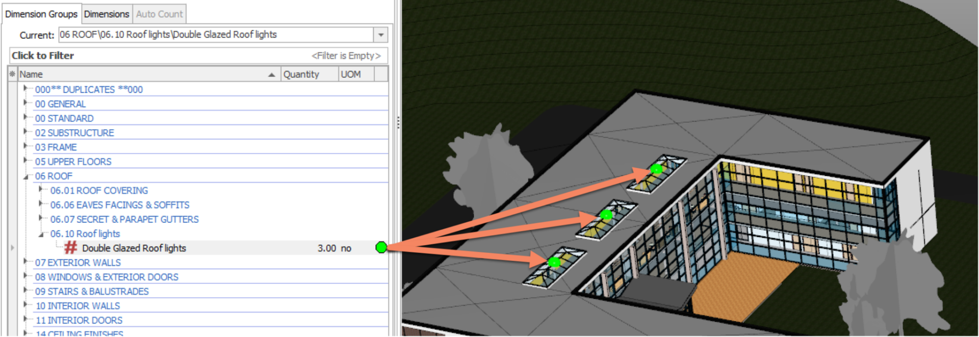
Length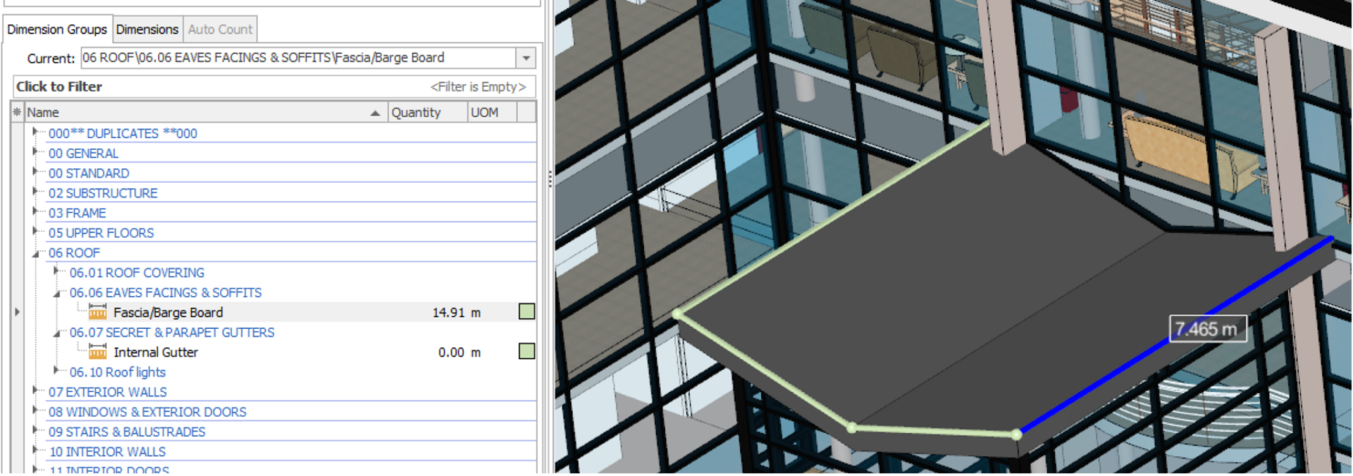
Area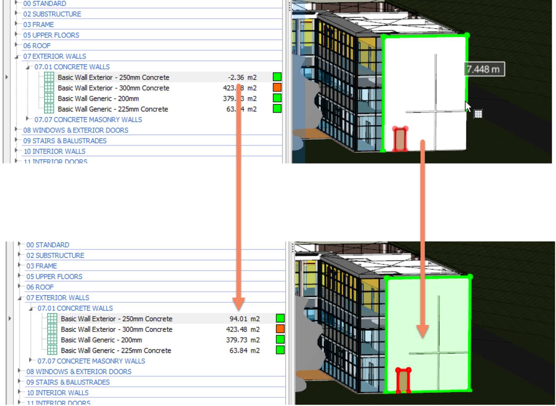
With this method dimensions with associated values are imported from object property values contained within the drawing file into the currently selected Dimension Group. This method requires the Dimension Group to be created and selected prior to importing dimension values. When the Dimension Group is created it is necessary to specify (map) which of the available object properties are imported and which Dimension Group value field they are imported into. Once the Dimension Group has been established the user can then choose the objects for which dimensions are to be imported by either selecting them individually, by selecting an area in the drawing window or by selecting one or more common properties with which to match (select) objects.
Selecting individual objects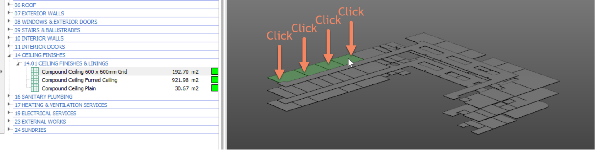
Selecting objects in an Area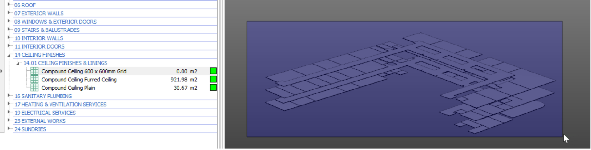
Selecting objects with one or more common properties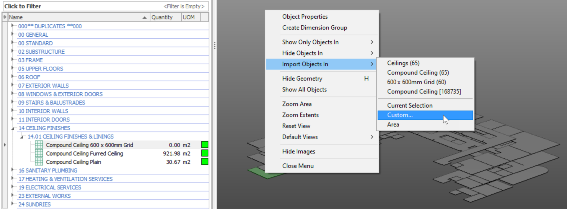
With this method Dimension Group folders and Dimension Groups are created automatically and dimensions with associated values are imported from object properties contained within the data model based on a set of rules contained within a BIM Import Template. The BIM Import Template specifies (maps) which of the available parametric object property values are imported and which Dimension Group value field they are imported into. The user can choose the objects for which dimensions are to be imported by filtering or hiding the displayed objects or layers before commencing the import process.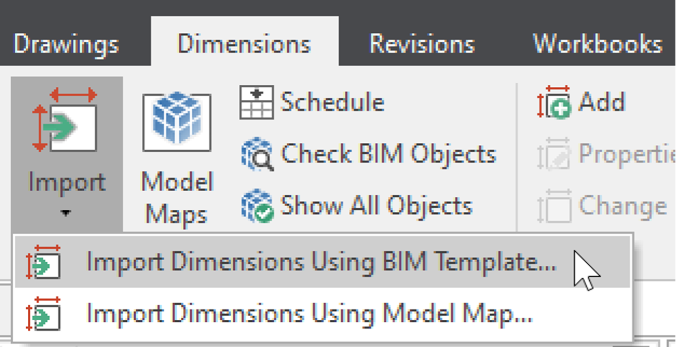
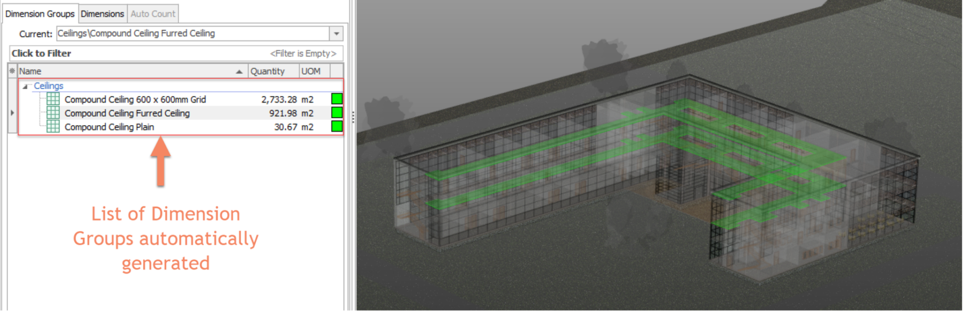
The above method is great for a high level ‘sanity check’ of quantities. The automatically generated Dimension Group Folders and Dimension Groups rely on the Model Tree structure of the model (provided by the designer) to match the requirements of how a Quantity Surveyor (QS) would typically measure. The structure of this model tree is not always suitable and therefore requires a QS to build their own ‘template’, better known as a ‘Model Map’, to ensure the generated Dimension Groups are in accordance with a desired standard.
With this method Dimension Group folders and Dimension Groups are created automatically and dimensions with associated values are imported from object properties contained within the data model based on a set of rules defined by the user in a Model Map. The Model Map allows the user to specify (map) for different groups of objects which of the available object properties are imported and which Dimension Group value field they are imported into. The user can choose the objects for which dimensions are to be imported by either selectively defining the Model Map, or by filtering or hiding the displayed objects or layers before commencing the import process.
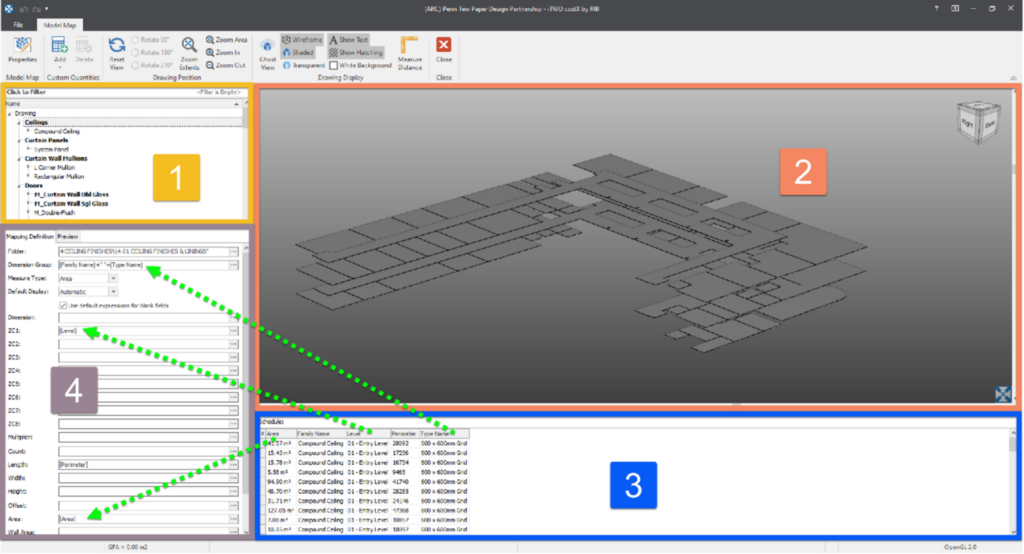
Below is an example which shows a high-level explanation on how this functionality works.
 This is referred to as the “Model Tree”. This tree is set and categorizes different elements of the model according to how the designer has categorised the tree structure. One would typically start by selecting an individual node (in this below example: “Ceilings”).
 This is referred to as the “Display Window”. This display window automatically filters to only show the objects which have been selected in the Model Tree.
 This is referred to as the “Schedule”. This is a schedule of all the information which is currently displayed in the display window. As the Display Window is filtering by selecting nodes in the Model Tree, so too is the Schedule. This is a schedule of object information provided by the designer.
 This is referred to as the “Mapping Definition” window. These are property fields of a Dimension Group. The term “Model Mapping” is used when the information from the Schedule is mapped into these Dimension Group fields via a Drag-and-drop process. Essentially, it’s taking the schedule of information provided to you by the designer (which may differ from one designer to the next) and giving the QS the ability to map it into a format that is suitable for how a QS might typically quantity elements. This gives the QS flexibility to measure (or extract) the quantities into a format that is in accordance with a Standard Method of Measurement.
These four methods each have their own use cases and can also be used in combination with one another. Every scenario might be different, and every model might be different. These different scenarios would determine which technique you might choose to use. Hopefully this provides a good introduction and a better understanding on the four different BIM measurement techniques in RIB CostX. If you are an existing RIB CostX user and this overview has sparked your interest, please feel free to go ahead and refer to our “Drawing File Optimization Document” or “Advanced Manual” which can be downloaded from our TechWeb page.

E-BOOK